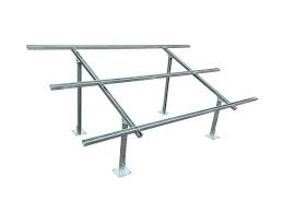
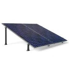
The solar PV mounting structure shall be a custom‑designed, hot‑dip galvanized steel structure to support framed PV modules at a fixed or adjustable tilt, suitable for rooftop or ground installation. The design must withstand site‑specific wind, seismic, and snow loads, and ensure long‑term durability in outdoor conditions.
The structure shall be designed, fabricated and tested according to the latest editions of applicable standards such as:
ISO / IEC 62548: Design requirements for PV support structures
ASCE 7: Minimum design loads for buildings and other structures
ASTM A123 / A153: Hot‑dip galvanized coatings
Local Building & Wind Codes: As per project location
Primary Frame: Cold‑formed/rolled sections or SHS/CHS structural steel
Material Grade: Minimum S235 / equivalent structural steel
Finish: Hot‑dip galvanized with average coating thickness ≥ 80–100 µm
Optional: Powder coating or epoxy primer for aggressive environments
Bolts, Nuts, Washers: Grade 8.8 or higher
Material: Stainless steel (SS304/SS316) recommended for all external fasteners
Clamps: PV module end & mid clamps compatible with panel frame thickness
Roof Mount: Anchor bolts (mechanical/chemical) into concrete/tile structures
Ground Mount: Concrete pads or driven piles as per geotechnical recommendation
| Parameter | Value / Requirement |
|---|---|
| Tilt Angle | Custom (e.g., 10°–30°) based on latitude & shading analysis |
| Orientation | Portrait / Landscape |
| Module Sizes Supported | e.g., 60‑cell / 72‑cell / Large Format |
| Design Wind Speed | e.g., 150–220 km/h (site specific) |
| Snow Load | As per local code (if applicable) |
| Seismic Design | As per local zone requirements |
| Corrosion Protection | Hot‑dip galvanization per ASTM |
| Service Life | ≥ 20 years |
The structure shall be designed to safely withstand:
Dead loads (self‑weight + PV modules + hardware)
Live loads (maintenance personnel)
Wind loads per ASCE/Local code
Snow loads (if applicable)
Seismic loads per local seismic coefficients
Maximum deflection of any structural member shall not exceed L/180 under service load.
All connections shall be bolted. Welds (if any) must be continuous and performed by certified welders.
All steel members shall be drilled and punched in workshop.
Sharp edges and burrs shall be removed before galvanizing.
After galvanizing, fittings must be assembled to ensure proper fit on site.
Provide detailed shop drawings with dimensions and part numbers.
Ensure correct anchor bolt layout for roof/ground.
Modules to be installed only after frame inspection.
Torque settings for bolts per manufacturer’s recommendation.
Ensure drainage and no penetration of roof waterproofing membrane (use proper flashing/boots).
No review given yet!
 Fast Delivery all across the country
 Safe Payment
 7 Days Return Policy
 100% Authentic Products


You need to Sign in to view this feature
This address will be removed from this list